Give the measurements a frame of reference.
A useful hand-tracking experiment needs more than a signal and an algorithm. It needs repeatable sensor placement, known distances, consistent camera reference views, and a structure that preserves those relationships. I designed the physical and documented foundation around that problem.
From the idea
to the implementation.
- 01
Define the sensing space
I set the hand/arm region, open-front access, sensor population, camera viewpoints, and measurement-reference requirements before treating the frame as a collection of printable parts.
- 02
Connect sensor positions to calibration
I made the origin, relative placements, sensor separations, and reference surfaces explicit in the design. The goal is to carry actual geometry through calibration and analysis instead of relying on schematic positions.
- 03
Engineer the fixture as an assembly
The CAD work connects a reinforced base, frame, sensor holders, camera mounts, fasteners, measurement panels, and cable routing. Optional expansion hardware is accounted for separately from the current configuration.
- 04
Turn the model into a buildable workflow
Print files, part identities, and final positions feed a guided assembly system. Its 27 stages and 81 actions make the sequence inspectable, while unverified insertion paths stay identified as placement views.
- 05
Define what the experiment must prove
Physical fit and dimensional checks precede reference-camera calibration and live sensing evaluation. The acceptance plan keeps structural design, repeatable measurements, and hand-tracking performance as distinct results.
The structure
is part of the instrument.
Every sensor needs a meaningful place. Every camera reference needs a relationship to that place. The fixture is designed to make those relationships measurable and repeatable.
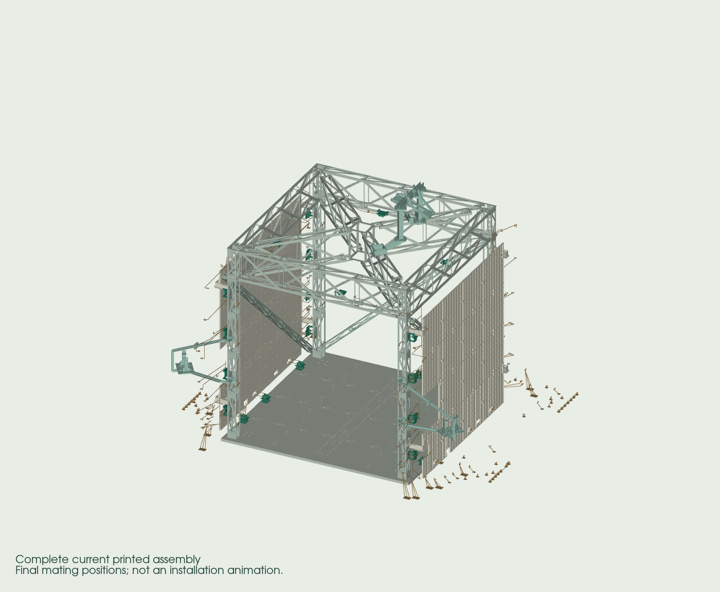
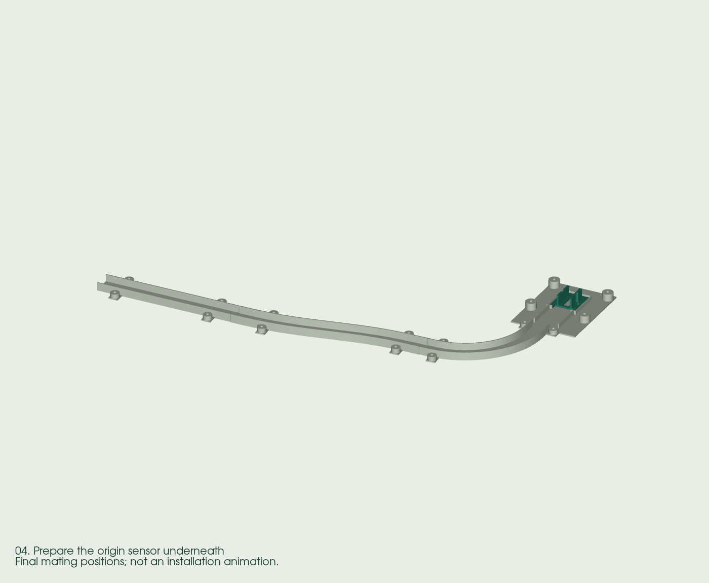
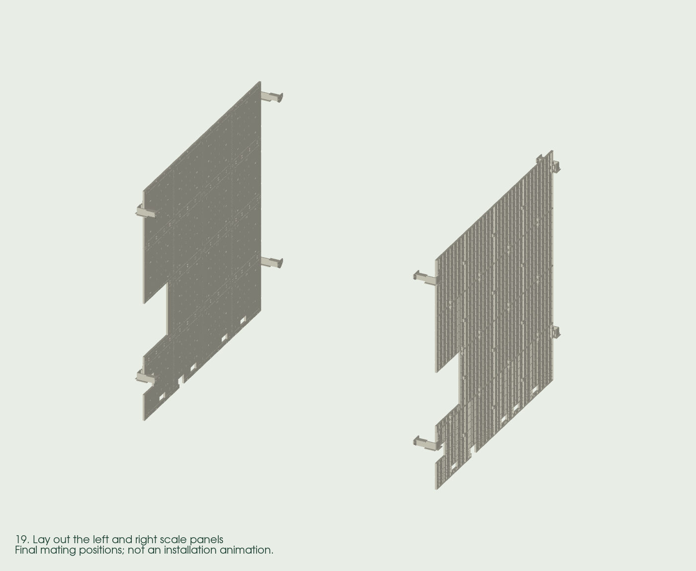
The delivered work is the sensing-platform design, print preparation and guided assembly workflow. Live hand-tracking performance is evaluated after the physical rig and reference geometry are qualified.
Decisions that
shape the system.
Make geometry part of the system
The fixture defines 28 sensor positions, a deliberate origin, and a 29.5-inch nominal clear interior. Sensor separations and placement are inputs to calibration and reconstruction, rather than assumptions hidden in a display.
Design the cameras into the experiment
Three camera positions provide reference viewpoints around the hand region. The frame, mounts and measurement surfaces are designed together so reference observations can be related to the RF layout.
Make the structure manufacturable
Separate printable components, mating features, holders, fasteners and cable routes connect the CAD model to an actual assembly plan. Print orientation and final installed orientation remain different parts of that workflow.
Make assembly understandable
A part-to-print-job index and guided stages connect each component to its place in the final structure. The digital guide supports playback, pause, replay, scrubbing, slower speed and reduced motion.
- Sensor placement
- Reference geometry
- RF observations
- Camera comparison
- Evaluate tracking
Inside the implementation
This is the hand-tracking fixture within the wider Radio Scans research program. Its central design choice is explicit geometry: a known sensor origin and relative placements, reference surfaces visible to the cameras, and a clear region for hand and arm motion. Nominal CAD positions define the intended arrangement; assembly measurements and calibration establish the real one. Subsequent RF estimates can then be compared with reference observations on a shared coordinate basis. The same distinction separates an informative reconstruction from an attractive picture.
What the work
demonstrates.
- Designed sensor positions
- 28
- Current camera positions
- 3
- Guided assembly stages
- 27
The project has an integrated fixture design, explicit sensor and camera geometry, measurement panels, print-job preparation, and an interactive assembly guide with 81 actions across 27 stages. These artifacts turn the sensing idea into a concrete experimental platform with traceable construction and validation requirements.
Why it matters to a client
Shows how I connect software research to the realities of hardware: geometry, manufacturing constraints, reference measurements, assembly instructions, and a test plan that can turn a prototype into reproducible evidence.